Phase Chip:
Control and Measurement of the Phase Behavior of Aqueous Solutions Using Microfluidics
Supplemental material to JACS 2007 (movies are below)
Selected by Editors' Choice, Science, 6 July 2007.
PhaseChip 2.0
Video of a presentation at the New York Academy of Sciences. Go to "media" tab.
Simple, robust storage of drops and fluids in a microfluidic device
And Movies!
 |
---------------------------------------------------------------------------------
---------------------------------------------------------------------------------|
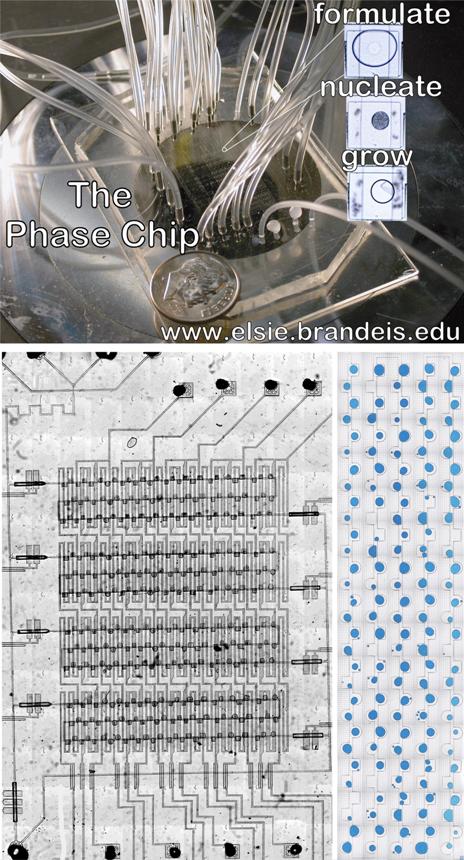
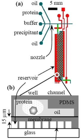
Movies of PhaseChip 1.0: JACS 2007 Figure S4.1. Drop formation. The Phase Chip is a poly(dimethylsiloxane) (PDMS) device which utilizes hydrodynamic focusing to produce drops of protein solution inside a continuous oil stream. This movie shows the nozzle, illustrated in Figure 1b. Channels are 100 microns wide and the drops are about 1 nl. This movie is not real time; drops are formed at 50 hz. The oil is introduced in channels on the top and bottom of the frame. The protein solution is premixed and enters from the right side of the frame. All fluids are driven by syringe pumps. The movie is an .avi file made with QuickTime. Protein solution in an oil inlet |
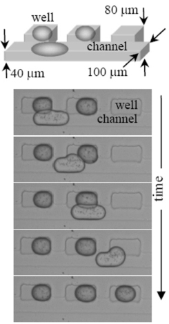
| Figure S4.2. Drop storage. One of the Phase Chip’s innovations is to exploit surface tension forces to guide each drop to a storage chamber, or well, illustrated in this movie and in Figure 1. The device is designed such that the channels flatten and elongate the drop. Wells, located to the side of the channel are deeper than the flow channel. A drop in a well can adopt shape that decreases its surface area and hence its surface energy. A drop that partially occupies both a channel and well will experience a gradient in surface energy, with the resulting force acting to drive and store the drop inside the well. As the wells exist as pockets on the sides of the channel, the enclosed, stored droplets are outside the flow stream and shielded from dislodgment by hydrodynamic forces. Drops sequentially fill the wells, with the first drop going into the first well. Subsequent drops pass over all filled wells, entering the first empty well. To prevent coalescence of the drops during the loading process, surfactants must be added to the bulk, continuous phase. In this movie, the oil is hexadecane and the surfactant is Span80 (2% w/v) ) and it was filmed at 2500 frames / sec. |
|
---------------------------------------------------------------------------------
Figure S4.3. Size matters.
Care must be taken to match the volume of the drop to the wells. If the docked drop is too large it will protrude into the channel and the next drop will dislodge it. If the docked drop is too small, a second drop will share its well. In this movie, the drop is half the volume of the rectangular wells located upstream. Subsequent drops displace the stored drop, creating a cascade. Downstream there are cylindrical wells which match the drop size so that docked drops are not displaced by subsequent drops. Note that the cylindrical wells have small slots at twelve and six o’clock. These allow the oil to drain out of the slots as the aqueous drops enter the wells. Without the slots the drops are sometimes blocked from entering the wells because the oil they are displacing has no exit path. In this movie, the oil is hexadecane and the surfactant is Span80 (2% w/v) and it was filmed at 2500 frames / sec.
---------------------------------------------------------------------------------
Figure S4.4. Drop storage without surfactant.
As in Figures 1 and S4.2, this storage method uses wells adjacent to, but connected to the flow channel. The drops flow by the wells when moving at high flow rates if the well is shallow in depth, comparable with the height of the flow channel. When the flow stops the drops spontaneously dock into the nearest well in a game of microfluidic musical chairs. In this method the first drop docks into the last well and the last drop docks into the first well. Without surfactant to stabilize the drop some mixing of drops occurs and typically the contents of about three or four adjacent drops are shared. In this movie a fluorinated oil (FC-43, 3M) mixed with a surfactant (12%w/w, Tridecafluoro octanol, Sigma-Aldrich) was used. The surfactant lowers surface tension making it easy to create drops and simultaneously slows coalescence of drops. Extraction of the drops from the wells is possible when the flow direction is reversed, making recovery of the droplets possible. The movie is recorded in real time.
---------------------------------------------------------------------------------
Figure S4.5. Liquid – Liquid phase transition.
In Figure 5 the liquid – liquid phase boundary of a PEG / ammonium salt mixture is mapped. In Figures 5b, c and d three images are shown of a single drop as water flows out and the solutes concentrate. Two wells, similar to the well shown in Figures 5b,c and d, are shown in this 24 hour time lapse movie. The drop starts out in the single phase region (Figure 5b). As the drops shrink they take on a bluish tinge as the dye is concentrated. At a certain point there is a sudden flash as the liquid-liquid phase boundary is crossed. Note that both drops cross the phase boundary simultaneously. As the drop further shrinks, the proportion of the dense liquid phase increases.
---------------------------------------------------------------------------------
Figure S4.6. Two step protein crystallization pathway.
A time lapse movie of the second from the rightmost well in Figure 7 is shown in this timelapse movie of 138 hour duration. The reservoir is filled with 6M NaCl solution for 42 hours. The initially large drop shrinks thereby increasing both the lysozyme and PEG concentration. The protein / polymer (lysozyme / PEG) mixture precipitates indicating this condition is deep in the supersaturation region. After 42 hours the reservoir is replaced with a 2M NaCl solution. The drops swell, diluting the solute concentrations. The drops first became clear and then a single crystal grows at the oil/water interface.
---------------------------------------------------------------------------------
| Figure S4.7. Crystal annealing. A crystal of xylanase is alternately grown and dissolved by varying the contents of the reservoir. The xylanase (Hampton Research, HR7-104), was dialyzed against 0.4M potassium sodium tartrate tetrahydrate (Hampton Research, Crystal Screen HR2-110) and the initial protein concentration was 15.3 mg/ml. Xylanase does not crystallize under these conditions. When the reservoir contains high salt, water flows out of the protein solution, dehydrating the protein solution and the crystal grows. When the reservoir contains low salt, water flows into the protein solution and the crystal dissolves. |
|